 Merry Christmas and Happy New Year!
 Friday, December 24, 2010
Friday, December 17, 2010
Revit - Surface pattern
 A question came up recently about how to remove the surface pattern from a slab when viewing it from a plan view.
First off, find out what the material is on the slab that is being displayed. Select the slab, go to "Edit Type" in the Properties. Under Structure row, pick the Edit button. Find the top material. Lets say concrete for our example. Pick on it and select the "..." button. This will open up the Materials. The select material should be pre-highlighted. Select it and go to the Surface Pattern area on the right. Change the material to . Select OK three times and you will be back to your view, which is now updated to not show the surface material.
Note: This will remove the surface pattern for all of the slabs with that same material. There are some other options to duplicate the slab type and material, if you want slab "A" to show surface material, and slab "B" not to show the surface material.
Wednesday, December 15, 2010
3ds Max Design
3ds Max Design can be like a "black box". But with a little understanding of the software, it can produce some very realistic images of your model. A question that may come up is whether to use Scanline or Mental Ray rendering. It may seem an odd question at the beginning of a project, but we need to start with the end in mind. Several of the materials, lighting and environment can be effected by which rendering engine is chosen.
Scanline has been around for several years and was the default rendering engine in 3ds Max. But Mental Ray, which is a contracted third party application for rendering that comes with the software, can tie together the materials, lighting and environment to adjust colors, and brightness for rendering. Many existing users of Max still use the Scanline because they are not that familiar with Mental Ray, but give it a try, see what results you can get. You may be pleasantly surprised!
Scanline has been around for several years and was the default rendering engine in 3ds Max. But Mental Ray, which is a contracted third party application for rendering that comes with the software, can tie together the materials, lighting and environment to adjust colors, and brightness for rendering. Many existing users of Max still use the Scanline because they are not that familiar with Mental Ray, but give it a try, see what results you can get. You may be pleasantly surprised!
Friday, December 10, 2010
Revit Server
 Revit Server is available thru Autodesk Subscription. It allows multiple users in seperate offices to access the same file. This is different than traditional Worksets. There are some specific requirements to have inplace forthis to work. IIS7, Windows Server 2008 (not r2), and this only works presently within your WAN.
This is a good link to Autodesk's website regarding Revit Server, and it has a few videos as well: http://usa.autodesk.com/adsk/servlet/ps/dl/item?linkID=9243099&id=15731389&siteID=123112
Thursday, December 9, 2010
Backburner
 Backburner is a batch network rendering utility that comes with 3ds Max and Maya. This is used when you want to render multiple images to several computers/nodes.
It has 3 main pieces. Manager, Monitor and Server. The Manager and Monitor are usually installed on the same computer. This is typically your computer that is running 3ds Max, but does not have to be. Some companies have a dedicated Graphics computer that would work well to have this installed on. Also the Server piece needs to be install on the computer nodes. The name Server is a bit misleading, because it infact gets installed on the workstation. A true network server doesn't really have a part in all of this. Also, 3ds Max needs to be installed on the computers with the Server piece. 3ds Max is needed to process the information. It does not need to be registered or licensed. You can install up to 9,999 installations of 3ds Max for the Rendering farm.
So the concept is that you have a 3ds Max model and want to render several shots or an animation. Go thru your regular process in Max that you would normally do to render, but at the end use the Batch Rendering to load your renderings and animations. Then select the checkbox "Net render" button in the lower left and then the "render" button to send the images to be processed. The Manager and Monitor will take over from there. They will pass on the images to the Server nodes for processing.
Here is a great link to Autodesk's website with two videos on Backburner: http://usa.autodesk.com/adsk/servlet/ps/dl/item?siteID=123112&id=14338791&linkID=10381719
Wednesday, December 8, 2010
AutoCAD - Scaling
 No its not a Mitsubishi car symbol. Its an icon of the cross section of a an architectural scale. The actual tool is for Annotative scaling of annotation objects like text, dimensions and graphical symbols. This feature was added a few releases ago, but I realized from teaching, that there are a lot of folks who are still working in Model Space, doing things the old way, and aren't aware of Annotative scaling.
By using the annotative scaling, it takes care of all the busy work of text sizes when changing scale. The quick, down and dirty of making it work, is to have all of these buttons turned on. They will lit up and showing the light bulb and lightening bolt in yellow once on. Also you need to be using Annotative text or dimensions. Set your scale and start drawing. The text and dims will display at the correct height per your settings and when you change the scale they will update. I last cool thing is that the text will scale according to the Viewport scale. Annotative scale rocks! Enjoy!!
Tuesday, December 7, 2010
AutoCAD - Get a grip!
 Using grips in AutoCAD can be a useful way of editing your objects. Whether you are moving an object or lengthening a line, grips can be faster than finding the traditional tools for editing.
When the grips are "blue" they are cold or not selected. When you select the grips, they turn red, or whats called "hot", which means they are active and ready for action.
In recent releases of AutoCAD, more features have been added to grip selection. For example, on a polyline, we can now edit Vertices. Which includes: adding, removing or stretching.
Monday, December 6, 2010
AutoCAD
 I've been using AutoCAD since Release 11, when it was DOS based. A lot has changed since then, and for the better! I enjoy finding new tips, tricks and little things to help make life easier.
Here is something simple but worth it. Osnap - Parallel. This Osnap allows you to draw a new line or object parallel to a reference object. You start the line command, and then using the Parallel Osnap hover over the reference line. You will see a symbol looking like this "//" over the line. It will disapear as you move off, but once you are lined up parallel with the reference line and your new line, the symbol will reappear and you can draw your line parallel. Simple but effective! Enjoy!
Thursday, December 2, 2010
Autodesk Project Photofly
 I recently was a lab assistant at Autodesk University for a unique class. Project Photofly from Autodesk Labs. It is a software that allows you to take digital photos of your project (inside or outside) and the application will stich them together to create a 3d model point cloud. You can then go into the model and set measurements and X,Y,Z orientation reference points. Once done refining the model you can export it out to DWG, FBX and a couple other file formats. This app. is currently in Autodesk Labs, which means it is still being refined, but you can check it out and see what you think. Here is a link to the site:
Wednesday, December 1, 2010
Autodesk University 2010
 Its that time of year again for Autodesk University in Las Vegas. AU as its known is a worldwide conference that covers a week worth of learning, networking and finding out about new technologies. I am teaching a Revit Structure class this year which should be fun. It covers the Truss feature in Revit Structure.
Here is a link to the main AU website: http://au.autodesk.com/
Monday, November 29, 2010
Revit Levels – Made Live
 Continuing from the previous blog about dead levels, we can make dead levels into live levels. This is done by going to the “View” tab, “Create” panel, “Plan View” dropdown, and selecting the “Floor Plans” tool. A dialog box will appear to match up a dead live with the new floor plan. This will create a floor plan for the dead level, making it live. The new level will show up in the Project Browser.
Friday, November 26, 2010
Revit Levels – Dead vs. Live

For Levels, we can create levels with floor plan views. Or we can create levels that do not have floor plans associated with them. These are usually used when you want to constrain or lock elements to the “dead” level, but do not need the floor plan. This could be a B.O. Steel level, or some other level for coordination. Live levels are shown with blue datum, while dead levels are shown as black datums.
Wednesday, November 24, 2010
Revit – Measuring
 There are times when you need to measure objects. There are two different ways to do this in Revit. The first is “Measure between Two References” and “Measure Along An Element”. For the first, select the two references, and a temporary dimension will display the measurement. For the second option, select the element and then click to measure along the element tool. You can use the “Tab” key to select other elements.
Tuesday, November 23, 2010
Revit
 Couple of quick tips for Revit when adding doors.
- Type "SM" to place doors at the midpoint of wall segments.
- Click on the "space bar" to flip the swing direction before final placement.
- After placement, use the flip arrows to adjust the direction and swing. See image to the right.
These same tips work for windows as well.
Monday, November 22, 2010
Navigating in Revit
When finding your way around a Revit project, it is important to do it efficiently, so you are not stuck in a corner or zoomed far out of your project. For quick zooming, hold down the Shift key with your middle mouse button. For panning, hold down the middle mouse button. If you like keyboard shortcuts, here are a few helpful ones:
ZR Zoom Region
ZO Zoom Out
ZA Zoom All
ZS Zoom Sheet
ZP Previous Pan/Zoom
ZR Zoom Region
ZO Zoom Out
ZA Zoom All
ZS Zoom Sheet
ZP Previous Pan/Zoom
Monday, November 8, 2010
TREX - Trim Extend
TREX - Trim Extend. In AutoCAD Express Tools, there was added a command named TREX. Commandline: TREX... Pick to trim or Shift+Pick to extend [Project/Edge/Undo]:
It was a combination of Trim and Extend by holding down the Shift key. That functionality is now part of base AutoCAD. Now you dont need Express Tools to have this option. Its included. Either in Trim or Extend you can use the Shift key to toggle between the two commands. I suggest using the "Select All" option for cutting edge at the beginning to give you the most functionality.
It was a combination of Trim and Extend by holding down the Shift key. That functionality is now part of base AutoCAD. Now you dont need Express Tools to have this option. Its included. Either in Trim or Extend you can use the Shift key to toggle between the two commands. I suggest using the "Select All" option for cutting edge at the beginning to give you the most functionality.
BATTMAN
 BATTMAN - Block Attribute Manager. From Autodesk Help... You can edit the attribute definitions in blocks, remove attributes from blocks, and change the order in which you are prompted for attribute values when inserting a block.
Attributes of the selected block are displayed in the attribute list. By default, Tag, Prompt, Default, Mode, and Annotative attribute properties are displayed in the attribute list. You can specify which attribute properties you want displayed in the list by choosing Settings.
For each selected block, a description below the attribute list identifies the number of its instances in the current drawing and in the current layout.
Thursday, November 4, 2010
Inventor - Tutorials
 For a "newbie" of Inventor I need all the hlep I can get. So I am glad to see a wealth of information on training in the form of Tutorials. This image to the side show some of the areas covered in the tutorials. From starting a project, navigation, assemblies all the way thru an entire project. I found some helpful content on Autodesk website in the Inventor section on learning resources as well. Cant wait to dive in!
Inventor - Getting Started
 After waiting what seemed like forever to download Inventor, I was ready to install the application. That went smoothly and now Im ready to start learning some new stuff. First off I felt somewhat comfortable with the application because of the Ribbon configuration. The first tab is a "Getting Started" tab with a dozen or so panels with items to help to get you off the ground. These look very informative, covering Ribbon intorduction, What's New, Tutorials and other helpful items. Be sure to take a look at them. Above is a screengrab to see what is listed.
Autodesk Inventor
 I usually work with Revit or 3ds Max, but recently have been interested in Inventor. For those of you familiar with Revit and BIM, the Inventor product is the parameteric modeling tool for Manufacturing.
Link to Autodesk's Inventor: http://usa.autodesk.com/adsk/servlet/pc/index?siteID=123112&id=13717655
Friday, October 29, 2010
ACA - Project Nav
 Recently a client issue came up: Their DWG files weren't coming across when creating a new project in Project Navigator.
The DWGs need to be in the project folders of the project that is being created from. Default for 2011 is: C:\ProgramData\Autodesk\ACA 2011\enu\Template\Commercial Template Project (Imperial)\Commercial Template Project (Imperial).apj. This APJ, with the DST location has all of the folders, with the DWGs in them. If you are starting from an empty project, the no need for the dwgs. The dwts need to be mapped in the Project Properties under templates.
ACA - Smart Titleblocks
 For ACA - AutoCAD Architecture, making "smart" titleblocks... You need to use Fields. You can edit the DWT for your sheets. Type FIELD at commandline. There is a long list of items that can be displayed on a sheet. Usually the CurrentSheetSet ones work best for proejct related items.
Select ok, and the text will be placed on to the sheet. They are updated during a save, plot or regen.
Thursday, October 28, 2010
AutoCAD - Help F1
 During a command in AutoCAD, if you need further assistance, select the F1 key. This will not only open up the Help menu, but it will open it up to the command you are working in.
AutoCAD - PEDIT
 PEDIT, or Polyline Edit will take seperate lines and arcs and glue them together to create a polyline. It will turn individual lines into Polyline. There are also subset commands in [brackets] to perform additional functions to the polyline.
AutoCAD - BPOLY
 Bpoly, or Boundary polyline is a great command to create a polyine based off an enclosed area. The fastest and most effective method of creating a boundary polyline is to use the island detection. As long as the area is enclosed, like for hacthing, yo ucan select the middle open area of lines and circles, and BPOLY will create a closed polyline on the current layer.
AutoCAD - Linetype Scale
 In AutoCAD or AutoCAD Architecture we can control the Linetype display or spacing. This control can be in either Model Space or PaperSpace.
For Modelspace linetype control, we use the command LTSCALE. This will change the scale factor of linetypes for all objects in a drawing. This can coinside with the Annotation scale of the drawing. A regeneration of the drawing is required after changing the LTSCALE. You can also use REA at the commandline for a quick keyboard shortcut to "Regen All" the drawing.
For Paperspace we look at using PSTLSCALE with a variable of 1 or 0. For 0 there is no linetype scaling. The linetype spacing is based off the modelspace of the drawing. For a setting of 1, the viewport controls the linetype scaling. So if you change the scale of your viewport, it will update the linetype spacing.
Someone might ask why use one method over the other. Well the advantages of using PSLTSCALE set to 1, is that when ever yo uchange the viewport scale, you lineweights will change as well. In the above example PSLTSCAL is set to 1. We have two different scales, but the linetype scale and spacing look the same. This is a consistancy many companies want to achieve.
Tuesday, October 26, 2010
Software Download option
 Autodesk has a Download Manager that is suppose to help when downloading large files. Most of the installation exe's are 2+ gig, so they are all large. The problem is that I talked with folks who have had problems with installing the Download Manager or they installed it and nothing happens. There is a link to the right that reads "Standard download method", but clicking that sometimes doesnt seem to do anything.
So, here is what I came across to to download the files without the Manager. In the past I have had to right click on the Download Manager when it says "Standard Download Method" and select Properties. Highlight the link information and paste into a new tab/browser page in Internet Explorer adn the nclick enter. This will open up the download dialog box to either save or run the application. This is not the best method, but one that has been successful for me. I hope it works for you as well!
Monday, October 18, 2010
AutoCAD - Tablet - I regress
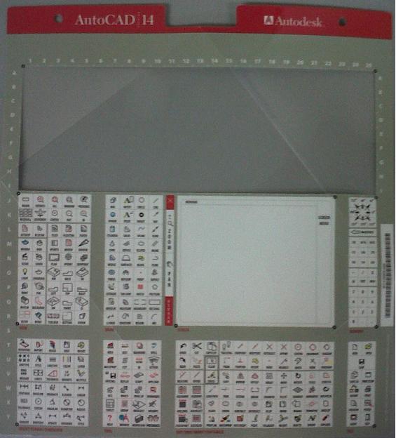 I found the fold up insert that came in the AutoCAD Release 14 box for tablet overlay. This is a real blast from the past. The overlay sat over top of the Digitizer tablet. The buttons could be programmed to make drawing faster. To bad AutoCAD and the computers at the time were so slow.
Life is easier using 2011. No Tablets. Now if I can find my old 24+ button puck around here somewhere?
AutoCAD - < > Greater Than / Less Than

No its not gang symbols. Its the greater than / less than symbols - hand gesture. I show my students this when teaching AutoCAD to get them into the thinking of using and thinking of these symbols because in AutoCAD in the commandline they represent the default value or last value used. Which menas you can save time by not having to do additional typing verces just hitting the enter key to accept whats in the "< >" value. So we can save additional time by using the default or previous used value by reading the commandline with the greater than and less than symbols "<>". Remember the graphic and save your self some time!
AutoCAD - Subset Commands
I taught a AutoCAD beginners class last week, in which I had a lot of fun teaching and sharing information about AutoCAD and how to make it work efficiently. One of the things I discovered quickly in the class is that half the students like "Button" commands, and the other half likes typing or knowing what the command were, or evern the shortcuts for them. Now I learned AutoCAD rel. 11, back in the day when it only came in a DOS version. We didnt have pretty picture buttons, so we had to learn the commands. I am thankful for this, because several of those same commands still apply and work today over 15 or so releases later. Continueing on this thought and in my class we discussed the Commandline. How it is your friend, and telling you the next thing to do, or atleast a suggestion. We also talked about the "Subset" commands or transparent commands that you can execute while actively in another command. Those are located in the commandline. Example below. You can type the capital letter of the subset command to activate it. This is a great way to save time. Some commands have options like Close, Undo, or Join, depending on the initial command you are in. IF you havent used these subset commands, give thme a try. Enjoy!
[SubsetCommandInBrackets]
[SubsetCommandInBrackets]
Thursday, October 14, 2010
Revit - BIMAssist
 BIMAssit is a Add-on for Revit. It was developed by Advanced Solutions Inc. This little set of tools really helps out with thefew short-comings in Revit. For example, the Door to Room linking capability. Wall Fire-rating coordination and Case Update to name a few. I've used this add-on and found it very helpful. And when working in Revit on a computer that did not have it I felt limited in what I could achieve. This add-on is well worth getting!
Here is a link for more information: https://www.advancedsolutionsonline.com:8445/bimassist_licensing
Wednesday, October 13, 2010
Laptop Crash
Usually I write about Autodesk software, but last night my laptop harddrive crashed and died. Luckily its under warranty, so a new harddrive is being sent out for me to put in. The bad thing is having to reinstall all my Autodesk software. So, I guess that is my tie in for the software side of things. But it is a good reminder to back up you files, on an external drive, online or CD/DVD. I thankfully had and old harddrive from a laptop that retired years ago, and bought a case for it with a USB cable. I have been using that for some time to copy important files, pictures, etc. in the event I had a crash or moving from one computer to another makes this an asy task. I also have a Western Digital External Book drive to back up big files like renderings, photos and the large several gig download installation from Autodesk. So the long and the short of the story is backup your files, and backup those files! It will make your life so much easier and stress free! Happy computing!
Tuesday, October 12, 2010
AutoCAD - Filters
AutoCAD filters are helpful but it seems arent used as much as they should be. Filters can be based off of Layer Propeties or Group. The Properties Filter is based off of the Layer criteria like: on/off, Name, Color, etc. This makes it easy to filter all of the red layers or layers that start with "A". For the Group filter, this is when the consistancy of layer criteria is mixed. We want to Group layers like A-Door with a color of green, and S-Grid with a color of red. There isnt a similarity between them, but we can pull them together in a Group.
Monday, October 11, 2010
AutoCAD - changing with the times
 AutoCAD... its been around so years and years. Continuely adding and changing. I started using AutoCAD in release 11, when there wasnt a Windows version. It only came in DOS. We used a puck for a mouse nad it had 24+ butotns on it. We also used something called a tablet which was a mouse pad metal box looking thing that had commands and drawing area on it. Now-a-days, when people mention tablets for CAD, they are talking about Tablet PCs or Ipad. Times have changed and so has the software, but many of the basic commands and tools I learned back then, I still use today.
Friday, October 8, 2010
Revit - Rendering
 Revit uses the "mental ray" rendering engine for producing realistic rendered images. "mental ray" is a third party application that comes with all Autodesk products. This "engine" is in 3ds Max as well which can create the extremely high end rendering, but sometime 3ds Max can be to involved with all of its settings. The nice thing about this powerful rendering engine in Revit is that it has been simplified. Not in its capabilites, but in the ease of its use. You dont have to be a lighting engineer to adjust the settings to get great results within the program. You shold be able to get some decent result within a few minutes when rendering in Revit. Best of luck and happy Rendering!
Thursday, October 7, 2010
Revit - Scope Box
 The Revit Scope Box allows for consistant extents of gridlines and datums thru out multiple levels in a project. Scope boxes control the visibility of datum elements in views whose cutting plane intersects the scope box. Scope boxes are particularly useful to control the visibility of datums that are not parallel or orthogonal to a view.
Scope boxes are automatically visible in 3D views and any view whose cut plane intersects the scope. They can also be set to display in elevation views. You can set their visibility for other views by resizing them or changing their visibility property. Scope boxes do not print in construction documents.
Wednesday, October 6, 2010
Revit - Phasing
 You can create as many phases as necessary and assign building model elements to specific phases. You can also make multiple copies of a view and apply different phases and phase filters to the different copies.
From the Autodesk Help file: Each view in Revit Architecture has a Phase property and a Phase Filter property.
The Phase property is the name of the view phase. When a view is opened or created, it automatically has a Phase value. You can copy a view and then select a different phase value for that view. For example, the original view has Phase 1; the copy has Phase 2. You create an element in Phase 1 and demolish it in Phase 2. The element displays as new in the original and as demolished in the copy. See Creating Phases.
The Phase Filter property lets you control the display of elements in a view. For example, demolished walls may display in blue dashed lines, while existing elements display in solid black lines. You can apply a phase filter to a view to see elements from one or more specified phases.
Tuesday, October 5, 2010
Revit - Linework Tool
 In Revit we need to be able to edit lines to give the sence of depth, especially in an elevation. The Linework Tool allows us to do that. The Linework tool does not create new model or detail lines in the view. Instead, it overrides the current line style of the selected line and applies a different line style.
You can use the Linework tool to change the line style of Projection edges of model elements, including silhouette edges and projection edges caused by plan regions
Monday, October 4, 2010
AutoCAD - Draworder
 Draworder, its been around for several releases, and is a great tool to use for stacking up hatches or text over hatches. Draworder changes the draw order of images and other objects. You can type DRAWORDER at the commandline or access the tools from the Draw Order Tool bar, along with getting the the tool fro mthe Modify Panel on the Home Tab.
Here is a link to Autodesk Support referring to Draworder: http://docs.autodesk.com/ACD/2011/ENU/filesACR/WS1a9193826455f5ffa23ce210c4a30acaf-4bce.htm
Friday, October 1, 2010
Revit - North - Project vs. True
 In Revit we can control the Project North vs True North and the orientation of the view associatedwith it.
From the Revit Help file "Drafting conventions dictate that Project North is the top of the view. If you need to change Project North, use the Rotate Project North tool. This tool changes Project North for all views in the project. "
1.Click Manage tabProject Location panelPosition drop-down Rotate Project North.
2.In the Rotate Project dialog, select the desired option.
3.Click OK.
Thursday, September 30, 2010
Revit - Guide Grids
 Guide Grids are new in 2011. They are designed to help in laying out of views on sheets. This is useful when tryign to line up floor plans on different sheets.
From Autodesk help "You can add guide grids to sheets to align views so that they appear in the same location from sheet to sheet. You can display the same guide grid in different sheet views. Guide grids can be shared between sheets. When new guide grids are created, they become available in the instance properties of sheets and can be applied to sheets. It is recommended to create only a few guide grids and then apply them to sheets. When you change the guide grid's properties/extents in one sheet, all the sheets which use that grid are updated accordingly."
Wednesday, September 29, 2010
Revit Server - Worksets
I wanted to share with you some new info I found out about “Revit-Server” This is something new that is coming out this week in the new web-update for the product. Also what is in this web-build update is an Energy Analysis component…
Revit Server is designed to help the workflow of distributed teams. And the Energy Analysis tool is bringing integrated energy analysis to Revit modeling. Making it possible to calculate massing to determine the best sustainable option.
Link to article: http://www.aecbytes.com/buildingthefuture/2010/RevitServer_CEA.html
Tuesday, September 28, 2010
AutoCAD - different approach
 AutoCAD is the base program that Autodesk wrote from scratch back in the early 80's. It is general purpose, meaning it can be used across several industries. That does not mean it is "general" in its capabilites. One of those unique approaches is drawing up colored elevations for products or equipment. The example to the left is one example of using gradient coloring in AutoCAD. AutoCAD now-a-days has industry specific tools for the different "flavors" of AutoCAD. See which one works best for you: http://usa.autodesk.com/adsk/servlet/pc/index?id=15408167&siteID=123112
Monday, September 27, 2010
Raster Design

I had the opportunity to play around with Raster Design tover the weekend. It is a great to for saving time for converting scanned images into Vector based linework. Here is what Autodesk says about it "Make the most of rasterized scanned drawings, maps, aerial photos, satellite imagery, and digital elevation models. With powerful raster editing and raster-to-vector conversion tools, AutoCAD® Raster Design software helps you to easily clean up, edit, enhance, and maintain scanned drawings and plans in a familiar AutoCAD® environment for use in AutoCAD®"
Find out more by follwong this link:
http://usa.autodesk.com/adsk/servlet/pc/index?id=2600114&siteID=123112
Friday, September 24, 2010
3ds Max - mental ray Proxies
 Need a stand in for your objects? This can help save time for rendering and when working in a scene file. Whats is it? mentalray Proxies in 3ds Max. They are a placeholders that are only loaded into memory and are processed per bucket during rendering. Files that use to lock up or freeze should now render quickly!
Go to the Create Panel , select "mental ray" in the Primitives drop down. Pick the "mr Proxy" button and place a box in the scene. Go to "Modify" panel and pick the "none" butto nto select the source object inthe scene. Then pick the "Write Object to File..." button to save the data of the object for rendering time. Atthis point everything is in place. Now you can copy, clone, or array the Proxy in your scene. You will see several boxes, but when you render they will all be nice rendered copies of the source object.
Wednesday, September 22, 2010
3ds Max - Ignore Backfacing
 Here is something for increasing your rendering time. Ignore Backfacing. From the Autodesk 3ds Max Help menu "When on, selection of sub-objects affects only those facing you. When off (the default), you can select any sub-object(s) under the mouse cursor, regardless of their visibility or facing. If there are more than one sub-object under the cursor, repeated clicking cycles through them. Likewise, with Ignore Backfacing off, region selection includes all sub-objects, regardless of the direction they face."
Tuesday, September 21, 2010
3ds Max
Couple of quick tips from todays class that I was teaching...
3d model rotate - hold down the Ctrl key and wheel mouse to spin the model.
Cloning - Move tool, hold down Shift. This will duplicate the object, but giving yo uthe option of Copy, Instance or Reference. Instance vs. Reference... Instance you can change any of the object copied and it updates all of them. Reference, you need to change the original, to update the oters.
Save Copy - This saves your scene and adds a number sequence to the end of the file name.
Monday, September 20, 2010
Autodesk - Alias

Autodesk Alias is a powerful creative modeling tool for the manufacturing industry.
Quote from Autodesk Alias website "Purpose-built for industrial designers and creative professionals, digital modelers/sculptors, and automotive/transportation designers, Autodesk® Alias® industrial design software products—Autodesk® Alias® Design, Autodesk® Alias® Surface, and Autodesk® Alias® Automotive software—provide a complete set of sketching, modeling, and 3D product visualization tools for the conceptual design process. Data integration and exchange with Autodesk® Inventor® software enables industrial design data to be incorporated into the digital prototype."
Quote from Autodesk Alias website "Purpose-built for industrial designers and creative professionals, digital modelers/sculptors, and automotive/transportation designers, Autodesk® Alias® industrial design software products—Autodesk® Alias® Design, Autodesk® Alias® Surface, and Autodesk® Alias® Automotive software—provide a complete set of sketching, modeling, and 3D product visualization tools for the conceptual design process. Data integration and exchange with Autodesk® Inventor® software enables industrial design data to be incorporated into the digital prototype."
Find out more about Autodesk Alias at: http://usa.autodesk.com/adsk/servlet/pc/index?id=14437167&siteID=123112
Friday, September 17, 2010
AIA NC Design Conference
 The AIA NC 2010 Design Conference in Asheville, NC
Quote from AIA NC website about the conference "The 2010 Design Conference will cater to the diverse needs of our membership. Many chances for exploration and learning are available as a backdrop to a conference that offers nationally known speakers, book signings, an exhibition of new green products, more than 12 HSW/SD credits, and recovery networking." Here is a link to the website: http://aianc.org/cde.cfm?event=314279
Thursday, September 16, 2010
Revit - Extension - Compare Models
 Looking into the Autodesk Subscription Add-in "Compare Models", we discover a powerful tool with the ability to detect changes, deletions and items that are equal.
From Help menu "Using the Compare models extension, you can compare 2 Revit models. The extension presents differences between successive versions of a structure project. When the extension starts, it recognizes the number of opened projects created in Revit. If more than 2 structure projects are opened, a dialog displays where you can select 2 projects to be compared."
Here is a link to learn more about Compare Models and other Extensions: http://www.extensions4revit.com/n/e4r/856/46
Wednesday, September 15, 2010
Revit - Wood Framing Walls
 Revit Architecture and Structure has some very helpful routines in the Exensions Manager for Subscription software members. One of those routines is the "Wood Framing Walls". This routine is catagorized under "Model" in the Exensions Manager. This powerful little routine makes framing a wall quick and easy. There is a good Help menu incase you need a bit more information on how to lay out the framing. Be sure to download this and other great tools from the Autodesk Subscription site.
Here is a link: http://subscription.autodesk.com/sp/servlet/public/index?siteID=11564774&id=11607975
Tuesday, September 14, 2010
Moldflow

I was tasked Friday and over the weekend to help set up for an Autodesk Moldflow class. Moldflow is an injection plastic 3d modeling software purchased by Autodesk. It is a very cool looking software. From Autodesk's website "Autodesk® Moldflow® simulation software provides injection molding simulation tools for optimizing plastic parts, injection molds, and the injection molding process. Autodesk Moldflow guides designers, mold makers, and engineers through simulation setup and results interpretation to show how changes to wall thickness, gate location, material, and geometry affect manufacturability. Autodesk Moldflow offers geometry support ranging from thin-walled parts to thick and solid applications and helps you to experiment with “what-if” scenarios before finalizing a design."
If you like modeling in 3d, check out more at Autodesk's website: http://www.moldflow.com/stp/
If you like modeling in 3d, check out more at Autodesk's website: http://www.moldflow.com/stp/
Revit Structure
 To create a brace frame in Revit Structure is best accomplished in a Framing elevation. Select the type of framing to add, like an HSS for metal building. But what do you do when yo uneed to show a Moment frame verces a Brace frame? After placing the brace framing, select the framing and go to Propoerties. Here yo ucan change the Connection Type to "Moment Frame". This will also change the graphical symbol in plan to show the filled in triangle, which is typical structural industry standard graphics.
Monday, September 13, 2010
Revit Structure - Grids
When creating grids in Revit Structure, be sure to use the "At Grids" option inder the "Multiple" column. This will save you a lot of time in placing the columns on gridlines. You can always go back and remove the extra columns you do not need.
Friday, September 10, 2010
Save down Revit file?

I was asked recently "If a drawing is done in Revit 2011 can it be opened and worked on in 2010?"
Officially... no. There isnt a save down or save earlier button in Revit. There never has been and probably never will be.
IFC to the rescue! You could export the project to IFC. Exporting to IFC is like breaking down the model into binary code. This allows other IFC-compliant applications to reassemble the code into its software application. So we can export from 2011 version, and import into 2010. This process may take a little time, but that is your only option.
Go to the Application Button (Big purple "R") dropdown, Export, IFC.
Link to Autodesk with further details: http://usa.autodesk.com/adsk/servlet/ps/dl/item?linkID=9243099&id=15649365&siteID=123112
Thursday, September 9, 2010
AutoCAD Revit Architecture Visualization Suite 2011

The Visualization Suite for AutoCAD/Revit Architecture includes: Revit Architecture, 3ds Max Design, Navisworks Simulate, AutoCAD Architecture and AutoCAD. All avaialable in 32 or 64 bit.
This is a great combo pack to get, and more than likely cheaper than buying them all seperately.
This is a great combo pack to get, and more than likely cheaper than buying them all seperately.
If you dont need 3ds MAx or Navisworks, then the Revit Architecture Suite is all you need. It comes with Revit Arch., AutoCAD Arch., and AutoCAD. Here is a link for more info:
Wednesday, September 8, 2010
FlexLM License server

Introduction
The purpose of this post is to explain how to update the FlexLM software to the latest version quickly, which at the time of this document is: 10.8. See screen grab below.
A word of caution
There are several ways to accomplish this task. This document addresses one of those methods. For further instructions or technical support contact Advanced Systems Inc.
Disclaimer
I hold no liability based of the actions of this post due to downtime, lost performance or other factors not allowing for a successfully completing the tasks here-in.
Preparation
Have other users who are using a network license get out of the software, or check out a license to keep them working and productive.
Copy the existing “?your company or release name?.lic” license file from the folder named “lic” or “License” depending on what was created. C:\Program Files\Autodesk Network License Manager\License to a temporary folder / safe place. We’ll need the license file later to merge with other products.
The data from the new lic. File needs to be copied and pasted into the existing lic. file.
The data from the new lic file should look like the below example:
SERVER Raiserver 002233e6674b
USE_SERVER
VENDOR adskflex port=2080
INCREMENT 51900AMECH_PP_2007_0F adskflex 1.000 permanent 3 \
VENDOR_STRING=commercial:permanent BORROW=4320 SUPERSEDE \
DUP_GROUP=UH ISSUED=19-Jan-2007 SN=123-22567483 SIGN="0341 \
9C3D D414 6A8D 8601 10DE A42D A847 43ED F1DB 60A0 08B7 D6F0 \
\
E672 8DE3 0F95 F1DE B0B7 05A9 9F17 58D7 DC92 A16D 51E1 D1F0 \
395B 1ED8 7175 D979 C9EB 7537 756E C332"
Stop the services on the server
Open FlexLM…
LMTools from start menu or from desktop
“Start/Stop/Read” Tab
The old License management software needs to be uninstalled. Add/Remove programs and uninstall it.
Once completed, the new license management software needs to be installed from the Autodesk application DVD.
Select Network install and then there should be an option to install network License Manager.
Copy the newly merged lic. file into the License folder.
Create a debug.log file and place it in the path: C:\Program Files\Autodesk Network License Manager
Configing FlexLM Services
LMTools from start menu or from desktop
Point the pathing to the files below. Use your lic file name.
Tuesday, September 7, 2010
DWG TrueConvert
 ABOUT
ABOUTDWG TrueView CAD file conversion software includes DWG TrueConvert™ translation software for translating any AutoCAD design application or AutoCAD-based drawing file for compatibility.
DOWNLOAD
Download the latest DWG Trueview from Autodesk’s website:
http://usa.autodesk.com/adsk/servlet/pc/index?siteID=123112&id=9078813
And install the software. Once installed, open the application…
CONVERTING DWGS
1. Open DWG TrueView 2010
2. Select the TrueView button from the upper left corner
3. DWG Convert dialog box will open. Pick the “Add File” button to add dwgs to the list.
4. Once file(s) are added select the button. And then “Modify”
5. The Modify Conversion setup dialog will allow you to pick the choices for saving your files to earlier versions and additional settings.
6. Once the changes have been made, select “OK” and then “Close”
7. Select “Convert” button to make the changes/conversions. Note: that the default setting is to convert the selected files in place.
8. So it wont look like anything has happened. But it has. You can verify this by clicking the “View Report” button in the lower left corner.
9. Done!
Friday, September 3, 2010
3ds Max - Panorama

The question came up the other day on how to make a panorama in 3ds Max. Here is the quick down and dirty.
1. Rendering dropdown Panorama Exporter
2. Command Panel
3. Select Rendering options
4. Once rendering is complete, use “Viewer…” button in the Panorama Exporter located in the Command Panel to view the Panorama. Hold down the left button to rotate the camera around the panorama
5. Export the Panorama… File Export. Choose from Cylinder, Sphere or QuickTime for file format. Note: full version of QuickTime is required.
Subscribe to:
Posts (Atom)