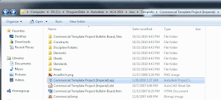
Recently a client issue came up: Their DWG files weren't coming across when creating a new project in Project Navigator.
The DWGs need to be in the project folders of the project that is being created from. Default for 2011 is: C:\ProgramData\Autodesk\ACA 2011\enu\Template\Commercial Template Project (Imperial)\Commercial Template Project (Imperial).apj. This APJ, with the DST location has all of the folders, with the DWGs in them. If you are starting from an empty project, the no need for the dwgs. The dwts need to be mapped in the Project Properties under templates.
Thoughts on Autodesk software... Revit, 3ds Max, AutoCAD, AutoCAD Architecture, Navisworks and the architecture industry.
Friday, October 29, 2010
ACA - Smart Titleblocks
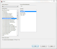
For ACA - AutoCAD Architecture, making "smart" titleblocks... You need to use Fields. You can edit the DWT for your sheets. Type FIELD at commandline. There is a long list of items that can be displayed on a sheet. Usually the CurrentSheetSet ones work best for proejct related items.
Select ok, and the text will be placed on to the sheet. They are updated during a save, plot or regen.
Thursday, October 28, 2010
AutoCAD - Help F1
AutoCAD - PEDIT
AutoCAD - BPOLY
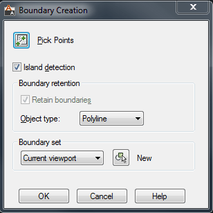
Bpoly, or Boundary polyline is a great command to create a polyine based off an enclosed area. The fastest and most effective method of creating a boundary polyline is to use the island detection. As long as the area is enclosed, like for hacthing, yo ucan select the middle open area of lines and circles, and BPOLY will create a closed polyline on the current layer.
AutoCAD - Linetype Scale
In AutoCAD or AutoCAD Architecture we can control the Linetype display or spacing. This control can be in either Model Space or PaperSpace.
For Modelspace linetype control, we use the command LTSCALE. This will change the scale factor of linetypes for all objects in a drawing. This can coinside with the Annotation scale of the drawing. A regeneration of the drawing is required after changing the LTSCALE. You can also use REA at the commandline for a quick keyboard shortcut to "Regen All" the drawing.
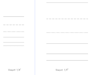
For Paperspace we look at using PSTLSCALE with a variable of 1 or 0. For 0 there is no linetype scaling. The linetype spacing is based off the modelspace of the drawing. For a setting of 1, the viewport controls the linetype scaling. So if you change the scale of your viewport, it will update the linetype spacing.
Someone might ask why use one method over the other. Well the advantages of using PSLTSCALE set to 1, is that when ever yo uchange the viewport scale, you lineweights will change as well. In the above example PSLTSCAL is set to 1. We have two different scales, but the linetype scale and spacing look the same. This is a consistancy many companies want to achieve.
Tuesday, October 26, 2010
Software Download option
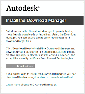
Autodesk has a Download Manager that is suppose to help when downloading large files. Most of the installation exe's are 2+ gig, so they are all large. The problem is that I talked with folks who have had problems with installing the Download Manager or they installed it and nothing happens. There is a link to the right that reads "Standard download method", but clicking that sometimes doesnt seem to do anything.
So, here is what I came across to to download the files without the Manager. In the past I have had to right click on the Download Manager when it says "Standard Download Method" and select Properties. Highlight the link information and paste into a new tab/browser page in Internet Explorer adn the nclick enter. This will open up the download dialog box to either save or run the application. This is not the best method, but one that has been successful for me. I hope it works for you as well!
Monday, October 18, 2010
AutoCAD - Tablet - I regress
I found the fold up insert that came in the AutoCAD Release 14 box for tablet overlay. This is a real blast from the past. The overlay sat over top of the Digitizer tablet. The buttons could be programmed to make drawing faster. To bad AutoCAD and the computers at the time were so slow.
Life is easier using 2011. No Tablets. Now if I can find my old 24+ button puck around here somewhere?
AutoCAD - < > Greater Than / Less Than
No its not gang symbols. Its the greater than / less than symbols - hand gesture. I show my students this when teaching AutoCAD to get them into the thinking of using and thinking of these symbols because in AutoCAD in the commandline they represent the default value or last value used. Which menas you can save time by not having to do additional typing verces just hitting the enter key to accept whats in the "< >" value. So we can save additional time by using the default or previous used value by reading the commandline with the greater than and less than symbols "<>". Remember the graphic and save your self some time!
AutoCAD - Subset Commands
I taught a AutoCAD beginners class last week, in which I had a lot of fun teaching and sharing information about AutoCAD and how to make it work efficiently. One of the things I discovered quickly in the class is that half the students like "Button" commands, and the other half likes typing or knowing what the command were, or evern the shortcuts for them. Now I learned AutoCAD rel. 11, back in the day when it only came in a DOS version. We didnt have pretty picture buttons, so we had to learn the commands. I am thankful for this, because several of those same commands still apply and work today over 15 or so releases later. Continueing on this thought and in my class we discussed the Commandline. How it is your friend, and telling you the next thing to do, or atleast a suggestion. We also talked about the "Subset" commands or transparent commands that you can execute while actively in another command. Those are located in the commandline. Example below. You can type the capital letter of the subset command to activate it. This is a great way to save time. Some commands have options like Close, Undo, or Join, depending on the initial command you are in. IF you havent used these subset commands, give thme a try. Enjoy!
[SubsetCommandInBrackets]
[SubsetCommandInBrackets]
Thursday, October 14, 2010
Revit - BIMAssist
BIMAssit is a Add-on for Revit. It was developed by Advanced Solutions Inc. This little set of tools really helps out with thefew short-comings in Revit. For example, the Door to Room linking capability. Wall Fire-rating coordination and Case Update to name a few. I've used this add-on and found it very helpful. And when working in Revit on a computer that did not have it I felt limited in what I could achieve. This add-on is well worth getting!
Here is a link for more information: https://www.advancedsolutionsonline.com:8445/bimassist_licensing
Wednesday, October 13, 2010
Laptop Crash
Usually I write about Autodesk software, but last night my laptop harddrive crashed and died. Luckily its under warranty, so a new harddrive is being sent out for me to put in. The bad thing is having to reinstall all my Autodesk software. So, I guess that is my tie in for the software side of things. But it is a good reminder to back up you files, on an external drive, online or CD/DVD. I thankfully had and old harddrive from a laptop that retired years ago, and bought a case for it with a USB cable. I have been using that for some time to copy important files, pictures, etc. in the event I had a crash or moving from one computer to another makes this an asy task. I also have a Western Digital External Book drive to back up big files like renderings, photos and the large several gig download installation from Autodesk. So the long and the short of the story is backup your files, and backup those files! It will make your life so much easier and stress free! Happy computing!
Tuesday, October 12, 2010
AutoCAD - Filters
AutoCAD filters are helpful but it seems arent used as much as they should be. Filters can be based off of Layer Propeties or Group. The Properties Filter is based off of the Layer criteria like: on/off, Name, Color, etc. This makes it easy to filter all of the red layers or layers that start with "A". For the Group filter, this is when the consistancy of layer criteria is mixed. We want to Group layers like A-Door with a color of green, and S-Grid with a color of red. There isnt a similarity between them, but we can pull them together in a Group.
Monday, October 11, 2010
AutoCAD - changing with the times
AutoCAD... its been around so years and years. Continuely adding and changing. I started using AutoCAD in release 11, when there wasnt a Windows version. It only came in DOS. We used a puck for a mouse nad it had 24+ butotns on it. We also used something called a tablet which was a mouse pad metal box looking thing that had commands and drawing area on it. Now-a-days, when people mention tablets for CAD, they are talking about Tablet PCs or Ipad. Times have changed and so has the software, but many of the basic commands and tools I learned back then, I still use today.
Friday, October 8, 2010
Revit - Rendering
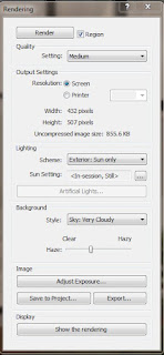
Revit uses the "mental ray" rendering engine for producing realistic rendered images. "mental ray" is a third party application that comes with all Autodesk products. This "engine" is in 3ds Max as well which can create the extremely high end rendering, but sometime 3ds Max can be to involved with all of its settings. The nice thing about this powerful rendering engine in Revit is that it has been simplified. Not in its capabilites, but in the ease of its use. You dont have to be a lighting engineer to adjust the settings to get great results within the program. You shold be able to get some decent result within a few minutes when rendering in Revit. Best of luck and happy Rendering!
Thursday, October 7, 2010
Revit - Scope Box
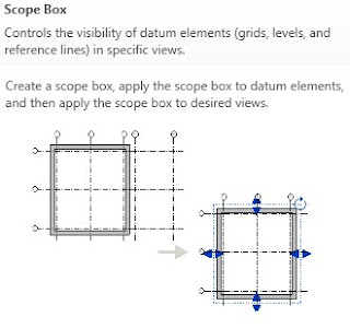
The Revit Scope Box allows for consistant extents of gridlines and datums thru out multiple levels in a project. Scope boxes control the visibility of datum elements in views whose cutting plane intersects the scope box. Scope boxes are particularly useful to control the visibility of datums that are not parallel or orthogonal to a view.
Scope boxes are automatically visible in 3D views and any view whose cut plane intersects the scope. They can also be set to display in elevation views. You can set their visibility for other views by resizing them or changing their visibility property. Scope boxes do not print in construction documents.
Wednesday, October 6, 2010
Revit - Phasing
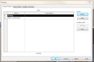
You can create as many phases as necessary and assign building model elements to specific phases. You can also make multiple copies of a view and apply different phases and phase filters to the different copies.
From the Autodesk Help file: Each view in Revit Architecture has a Phase property and a Phase Filter property.
The Phase property is the name of the view phase. When a view is opened or created, it automatically has a Phase value. You can copy a view and then select a different phase value for that view. For example, the original view has Phase 1; the copy has Phase 2. You create an element in Phase 1 and demolish it in Phase 2. The element displays as new in the original and as demolished in the copy. See Creating Phases.
The Phase Filter property lets you control the display of elements in a view. For example, demolished walls may display in blue dashed lines, while existing elements display in solid black lines. You can apply a phase filter to a view to see elements from one or more specified phases.
Tuesday, October 5, 2010
Revit - Linework Tool
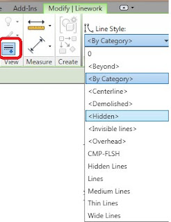
In Revit we need to be able to edit lines to give the sence of depth, especially in an elevation. The Linework Tool allows us to do that. The Linework tool does not create new model or detail lines in the view. Instead, it overrides the current line style of the selected line and applies a different line style.
You can use the Linework tool to change the line style of Projection edges of model elements, including silhouette edges and projection edges caused by plan regions
Monday, October 4, 2010
AutoCAD - Draworder
Draworder, its been around for several releases, and is a great tool to use for stacking up hatches or text over hatches. Draworder changes the draw order of images and other objects. You can type DRAWORDER at the commandline or access the tools from the Draw Order Tool bar, along with getting the the tool fro mthe Modify Panel on the Home Tab.
Here is a link to Autodesk Support referring to Draworder: http://docs.autodesk.com/ACD/2011/ENU/filesACR/WS1a9193826455f5ffa23ce210c4a30acaf-4bce.htm
Friday, October 1, 2010
Revit - North - Project vs. True
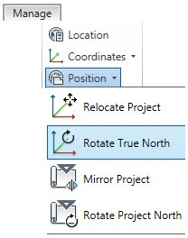
In Revit we can control the Project North vs True North and the orientation of the view associatedwith it.
From the Revit Help file "Drafting conventions dictate that Project North is the top of the view. If you need to change Project North, use the Rotate Project North tool. This tool changes Project North for all views in the project. "
1.Click Manage tabProject Location panelPosition drop-down Rotate Project North.
2.In the Rotate Project dialog, select the desired option.
3.Click OK.
Subscribe to:
Posts (Atom)